The Max Microchip Project- Investigating the Secrets of Implantable Pet ID Devices


I started the Max Microchip Project in 2005 as my answer to a call made by the U.S. Congress for a solution to a problem that is mostly unique to the United States, although most of the project may be applicable anywhere there is interest in an easy-to-build RFID microchip reader/scanner for identifying stray pets.

What's the problem in the U.S.? In most other countries, when a dog or cat owner takes his pet to a veterinarian to have a permanent under-skin identification transponder (or "microchip") implanted, there are several different types that may be used, but with few exceptions (Possibly China and Columbia???) the chips used outside the U.S. are types that are, by design, relatively easy to make a scanner for. That means the pet finder doesn't need to have any secret technology in his scanning device.

But in the U.S., lots of vets have implanted pets with a type made deliberately hard to decode- the "AVID" brand "Encrypted" microchip. Although supposedly equipped with encryption to prevent counterfeiting and cloning, I found this not to be true. Rather, these chips have "Obfuscation Encryption." It's easy to extract enough information from the chip to make a counterfeit of it; only the method/algorithm for converting the chip's transmissions to its original label code remains a closely guarded secret. So U.S. practice basically expects the volunteer stranger who tries to return a lost pet to supply these well hidden secrets. The pet finder trying to obtain the registry code of a found pet with an obfuscation-coded ID chip has a choice of using a scanner actually made by AVID itself, or by one of a small number of others that have the secrets, but not a scanner originating outside of AVID's cartel.

(To be fair, some U.S. vets do use non-obfuscated "Open Microchip Technology" chip types. In fact, all three of the common O.M.T. types have been used in the U.S., distributed by organizations such as HomeAgain and AKC-CAR. But Cartel-coded pets still number in the millions by most counts.)

Since I began the project, the list of scanner manufacturers that have the secret algorithm needed to read the obfuscation-type chips has added a few new members, with even AVID's big rival Datamars getting in somehow. So more brands of versatile scanners are now available to choose from, each with ability to give the label code for Encrypted-type and also to read several O.M.T. types. A downside of this development, visible to those who recognize the Obfuscation-Encrypted chip system as a defective product, is that now as before, each new Cartel Scanner is a machine for covering up that defect. A shelter volunteer can scan several dogs, each with a different type of chip, with one of the new scanners, and get the original label codes for each, but is never given any hint that one of them would be unobtainable to a pet rescuer without a Cartel scanner.

In contrast, the Max Microchip project's scanner has always been a machine for exposing the true nature of the "Encrypted" chips. It gives the original label codes for the three common types of open standard pet chips, and for the "Encrypted" type it produces a code made according to my "rec.pets-2005a" open standard.

My submitted solution to the 2005 Congressional "Open Microchip Technology" directive was to point out that if you simply recognize/define the output produced by a "rec.pets-2005a" compliant scanner to be the found pet's true recovery ID, that puts those millions of cartel-chip implanted pets into compliance with the Open Microchip Technology Directive, instantly without surgery. This would require Registry Operators (like the AKC-CAR and HomeAgain and any others that accept registrations of cartel-coded pets) to begin using the Max Microchip translator machine (or equivalent) for found animal reports made by pet rescuers with Open Technology scanners. Cartel scanners would not be outlawed, of course; pet rescuers would have a choice of which kind to use.

The USDA division that was asked by Congress to find a solution to the problem finally made its report in mid-2007, and it was a little weird; their solution seems to be, waiting for PATENTS to expire. But will that work? Could the decryption algorithm be part of a patent? (Hint: the algorithm is a SECRET; patents are public documents...) While the USDA may still be slacking off, this may be the year that the private pet chip registries (at least the more reputable ones) move into compliance with the OMT directive on their own by adopting the translator machine or some other approach.

As of 2008, many U.S. veterinarians still consider it quite reasonable to expect the volunteer stranger who tries to return a lost pet to provide a scanner with Cartel secrets; they're still poking puppies with the obfuscation-type chips.

Look here for a current annotated mark-up of Andy's proposed Open Standards work-around for "encrypted" pet identification microchips originally submitted to A.P.H.I.S. in 2006

More on the Max Microchip Concept:

The Max Microchip scanner is intended to be an easy-to-build project for hobby and educational use, so its performance shouldn't be expected to be animal shelter-grade in detection range, but it should be good enough (about 1/2 inch range) for use on calm animals if the microchip hasn't moved far from its proper location right under the skin of the neck/shoulders. Only basic tools are required, and you can build it without using a soldering iron. At some point, I may publish a more powerful version later, but it may require parts you can't get at the Radio Shack. The hardware design hasn't changed since its original release in mid-2006, but the software is now available as a new open-source version with Linux support.

There are a few things to learn before undertaking the project. The biggest piece of misinformation or disinformation you're likely to find if you research these chips has to do with the so-called "125 Kilohertz and 134.2 Kilohertz microchips." If you read the Web or other media about these chips, you're likely to arrive at an understanding that goes something like this: "Pet microchips are divided into two major categories, the 125 kHz and 134.2 kHz types. The 125 kHz types transmit their data at 125 kHz and use 125 kHz technology. The 134.2 kHz types transmit their data at 134.2 kHz and use 134.2 kHz technology. Obviously this makes it very complicated to build a universal scanner device, because you need to work at two different frequencies with two different technologies which are incompatible." The real story is more like this: "All the types of microchip commonly used for pets transmit their data by modulating a continuous oscillating magnetic field provided by the scanner device, at whatever frequency that device provides, if it's close enough to what the chip is tuned for. There certainly are types of transponders/chips that by their specifications are supposed to be tuned for one frequency or the other, but they're not so tightly tuned that you can't read a chip at all when driving it with the opposite frequency." Using a compromise frequency like 126 to 129 kHz can work fine, and even if you use exactly 125 kHz to optimize performance with the older, and generally weaker, chip types, you can still get good performance reading the newer 134.2 kHz types. For an extreme test, I got a couple of chips designed for 400 kHz use. These apparently were considered for use in pets around the late 1980's but lately have been limited to things like salmon tracking operations. I found that when pressed right up against a pick-up coil operating at 125 to 128 kHz, they gave a small but useable signal. Anyway, for the common pet chip types, a compromise frequency works fine. Tune your unit for something between 123 and 127 and you should be OK.

It's also helpful to learn something about two international standards, ISO 11784 and ISO 11785. Several of the types of transponders supported by the Max Microchip unit are types that speak one of the languages described by these, or a related "inverted" or "backwards" language that is also commonly used in pet ID chips in the U.S. Sometime you may want to peruse my separate page for info about these ISO standards. It describes in some detail which ISO-related transponder types are supported by the Max Microchip unit, and how to interpret its output when it finds one.

To round out the list of transponder protocols supported by the Max Microchip reader/scanner, we have support for the rec.pets-2005a standard. Unlike the ISO standards, this one is a real open standard; you don't have to pay for the privilege of reading it on the web. (See it here) And who wrote it? I did. (You can write an open standard too, if you like; I wrote mine in 2005.) This standard describes a method for reading a transponder such as the common AVID Brand "Encrypted" microchip, and outputting a true representation of what the chip is transmitting. Actually it supports reading a class of transponders of which the common "Encrypted" microchip is expected to be a subset. "Encrypted"-type transponders produce a unique output, called the "Primary Form" in the Standard, of 17 alphanumeric characters in length when read by a rec.pets-2005a reader/scanner such as the Max Microchip. The standard specifies an encoding method used to make this primary form from what the chip transmits. The Max Microchip reader/scanner program will also output the standard's Long Form, which gives each chip's code as 96 characters, which are all L's and H's. The Long Form is not very practical for general use; it is provided for backup, in anticipation of people who will say, "Your output is in code just like AVID's, only different." The optional Long Form is not encoded; it's a direct listing of what was demodulated from the chip. (If you hold the coil in place over the transponder, the Max Microchip will repeatedly print the Primary Form result, but will not repeat the Long Form unless there is a change to report, such as a different transponder.

But what good is a chip scanner that outputs a different code from the "label code" that came with the chip originally? It won't match what's in the pet registry database! The short answer is, for reporting a found stray pet to a registry or any authority, the right way to report is always by the actual identifying characteristics of the animal. That's what rec.pets-2005a lets you do. A pet registry has a duty to the pet owner; if it expects the pet finder to supply an obscure coding algorithm (in the form of a proprietary reader/scanner) just to make his report, the registry is remiss in its duty. But is it possible for a pet registry to accept the "actual identifying characteristics" of found pets by open microchip technology if it wants to? Sure, it just needs to have a translator machine.

For a longer answer, consider this. The AVID Brand "Encrypted" microchip is similar to all other types of pet identification transponders in many ways: 1. It imparts to the chipped animal a useful and unique new identifying characteristic in the form of a modulated signal that it transmits when activated. 2. That modulated signal can be converted to a unique code number, by whoever finds the lost pet using a scanner built according to publicly available open standards. (For the case of the AVID chip, I had to make up and publish the open standard myself. In theory lots of people could have made one up, but no one else seems to have bothered.) 3. The chip comes supplied with a sticker with a code number on it. And finally: 4. The pet owner is urged to register the code number on the sticker with a recovery database to which the eventual pet finder can send his scanned result. The difference between the "Encrypted" type and the other types is, the code number on its sticker is not the true identifying characteristic of the animal, because it can't be obtained from the modulated signal without secret information- the decryption algorithm. Is it reasonable to expect the pet rescuer, the guy who befriends the strays, to supply this secret algorithm, by buying a specific manufacturer's scanner product? Not if it's possible for the recovery database operator to do the decryption job by using a translator machine. And how do you build a translator machine? Think about it. Each of the reader/scanner devices that AVID makes for reading its transponders is a translator machine. It only lacks the part where you type in the value to be translated. This part can be added without too much trouble, to produce a basic, manually operated, translator machine. A more automated, internet-accessible translator machine, made by putting an "Encrypted"-type scanner on the web, is possible also, but would be more complicated to build, and you'd probably need to use a soldering iron.

The project can also be useful for demonstrating the nature of the AVID chip's "encryption" properties themselves. If monitoring the chip for a second or so with crude apparatus yields enough information to later feed into an AVID scanner and make it output the chip's original "cartel code," that would seem to indicate the chip had no Authentication Encryption features to prevent counterfeiting, but only Obfuscation Encryption. Obfuscation Encryption is what prevents you, the pet rescuer, from extracting a lost pet's original label code unless you are a member of the Cartel that knows the decryption secrets or have one of their products. If my rec.pets-2005a or some similar Open Standard gets adopted by the USDA/APHIS as I have proposed, the Open Standard code will be an officially accepted form, as it rightly should be, until the obfuscation/decryption secrets become public.

My work-around system of open microchip technology may not be for everyone, though. Suppose you're the manager of the Daisy Hill Puppy Farm, (That's the birthplace of SNOOPY, don't you know.) and you are using the current closed microchip technology with "Encrypted"-type chips and scanners. Your reaction to the rec.pets-2005a standard might be something like this, and I would say understandably so: "I bought the Encrypted scanners and chips for my operation years ago because the Kennel Club accepts it for identification requirements, it was readily available, friends recommended it, and it works great. Now you tell me that each dog has a different number that's the real number? It looks like a Bogus Code to me." That's one point of view. But consider the point of view of the pet rescuer, (here meaning, anyone who tries to find the owner of a stray pet) who may find one of the dogs from the Puppy Farm after it has been adopted and then has run away from home. He might say, "You didn't ask me if encryption was a good idea. I can easily read what this dog's chip is transmitting, but if the pet registry requires me to make my report with the result of a secret algorithm that only certain scanner manufacturers know, that's like asking me to translate a collar tag into an obscure unknown ancient language. The open technology reading is the animal's true identifying characteristic. Anything else is a Bogus Code." The pet rescuer's point of view is the one that deserves to carry the day, because he's always been the volunteer who makes the whole system work. (I would suggest that if you have a pet with an "Encrypted"-type transponder, you might want to check with your registry to find out if they will be accepting found pet reports by open technology such as rec.pets-2005a, or continue to accept only the proprietary codes.) Open Technology scanners built on the Max Microchip concept aren't a replacement for the proprietary decrypting scanners for all purposes. Many breeders and clinics, for example, will still want scanners that give the label code. Indeed, people in general will use whatever scanners they've got, or can get, but... The Max Microchip concept is the only solution so far for people who simply think found pets should be reported by their true identifying characteristics, or for people who want to have a universal scanner without getting it from the Cartel.

You may ask, how does the Max Microchip concept affect the directive by the U.S. Congress to the Department of Agriculture to implement a "system of open microchip technology in which all scanners can read all chips"? (search for "microchip" in this page) Well, what it does is, it demonstrates that implementing such a result does not require rechipping any pets. (Or outlawing pets with the "wrong" chips, or waiting for them to DIE!) As I suggested during the 2006 U.S. APHIS call for Comments, the Max Microchip concept, upgraded to create a new Open Standard Shelter Grade scanner design, can meet the requirement. It would do this by supporting the ISO-standard-related chip types, (which include the common HomeAgain chip among others) along with open standard rec.pets-2005a or some similar open standard for legacy "Encrypted" chips. (Maybe somebody wrote one before me that I didn't know about, or somebody will write a better one?) Some sources I have read seem to imply that fulfilling the open microchip technology directive is somehow difficult. In reality, it doesn't even require the Government to make a decision on a specific transponder type. It only requires official recognition that the Pet Rescuer's point of view (in the previous paragraph) is the valid one. Meaning, an Open Microchip Technology reading of an animal is its Real Recovery ID, and proprietary forms are not. New shelter-grade All-Chip open scanners would need to be designed and distributed, and we probably would want to have public access translator machines on the Web, but the important thing is, no surgery. Of course, if the secret decryption algorithm were published as an open standard, the proprietary form would be an Open Microchip Technology reading, and we could forget about the other forms.

Construction Details for the Max Microchip scanner and Translator Machine

If you'd like to build yourself a Max Microchip reader/scanner or Translator Machine, first please read my disclaimers.

All information related to these projects is provided as-is with no warranty. The builder must take all responsibility for determining the suitability of the information provided.

What are some examples of what the designer takes no responsibility for? Just for example, there is no warranty that the information or designs will be free of claims of patent or other "intellectual property" infringement in any country. There is no representation made that the level of escaping radio frequency energy will meet the legal limits of any country or that any compliance testing has been done. (In the U.S., the requirement that equipment using radio frequency energy must be tested by a recognized laboratory may have exemptions for hobbyist projects made in small quantities and not built from a kit, but that determination is up to you.)

Building electronic projects, even without using a soldering iron, may expose you to lead, a substance known to the state of California to be harmful to your health. It's bad for you in other states too. Wash hands after handling.

High voltages near and possibly above the levels commonly accepted as safe to touch may appear in the circuitry of the Max Microchip reader/scanner. Around 45 Volts DC and 30 Volts AC is normally seen at points on the breadboard socket, terminal strip, and dual modular outlet. It may be higher in some cases. Suitable protection, such as a box enclosure, should be provided. Likewise the insulation on the main coil must not be compromised.

The original 2006 copyrighted Max Microchip software is licensed to the public for hobbyist, educational, and pet rescue/recovery use by individuals and pet rescue organizations and by pet registry operators. No other use, such as commercial product use, is permitted without specific license. The 2008 open source version is subject to the GNU Public License.

The Max Microchip reader/scanner is not designed to be a Shelter-Grade product. It's designed to be a lost pet's first chance for recovery when found by the experimenter, not a stray's last chance at the Dog Pound. The current scanner project design produces a tabletop demonstration unit with pickup coil on a short tether. It is left up to the builder how to package it if something more portable is desired.

Read the complete instructions first, and decide if you want to alter the design any. If you don't require this to be a no-soldering project, you can replace the solderless breadboard socket with a blank printed circuit board. Also, there are many types of power switch you can choose to wire in with a soldering iron; you don't have to choose the miniature Frankenstein-style knife switch which hooks up without soldering. Actually, you may find a nice toggle switch with screw terminals at an auto parts store you can substitute even if not soldering. (Or you can just bypass and eliminate the switch altogether.) If your town has a cool independent electronic parts shop, that has resistors, capacitors, and other parts in bins, you might try taking your parts list there. Building without soldering and using only Radio Shack parts is not the cheapest way to build, just the most universal.

(You may find a type of solderless breadboard socket that has an extra connection column on each side compared to the one in my pictures. You can ignore the extra outer connection columns if you get one of these, but even the close-in vertical connection columns will be an extra tenth of an inch separated from the inner grids. This may require forming the leads of the parts differently from the pictures. Making the lead wires of the capacitors longer than shown and carefully forming them as needed is OK, and may be necessary to support the wider style of breadboard socket or capacitors with different lead spacing.)

Parts List for the Max Microchip Reader/Scanner

Putting it Together

Unpack your parts. Observe the difference between the 100 Picofarad Capacitor (probably has markings which include "100" or "101") and the similar 0.1 Microfarad Capacitors (probably have markings which include "0.1" or ".1" or "104") and cut the wire leads of all five capacitors as shown. The 0.01 Microfarad Capacitors (probably have markings which include "0.01" or ".01" or "103") are dark green in these pictures. Also form and cut the wire leads on the 22 Ohm resistor (coded Red-Red-Black-Gold.) Form and cut the wire leads on three 10000 Ohm resistors (coded Brown-Black-Orange-Gold) and one 47000 Ohm resistor (coded Yellow-Violet-Orange-Gold) as in the picture. Also form and cut to size a little jumper wire section as shown at the top left of the picture from one of the discarded cut off pieces.


Now install all the formed parts and the little jumper wire piece as shown in the picture below. Use your three formed 10000 Ohm resistors, the short, medium, and long one as appropriate. The 100 Picofarad Capacitor goes up in row 2 near the top; the 0.1 Microfarad Capacitors go farther down; and the 0.01 Microfarad Capacitors are in between, with each having one leg in row 6. Also insert the integrated circuit type LM386. The correct top end of the LM386 should have a notch in it, or else there should be a tiny round indentation where the pink dot shows in the picture. This indicates "Pin 1."


Form and cut the wire leads of one more 10000 Ohm resistor (coded Brown-Black-Orange-Gold) and one more 47000 Ohm resistor (coded Yellow-Violet-Orange-Gold) as in the picture below. Carefully separate out six of the fragile glass diodes. Straighten their wire leads and remove all of the sticky tape residue from the ends of the wires. Don't leave any. Form and cut one diode like the one at lower right in the picture. Then form and cut a total of five diodes shaped like the one at the very bottom of the picture. Be careful not to twist and put pressure on the glass part; after you bend one end of each diode, hold the first bend and try to get the second bend in symmetry with the first, so you won't have to twist to fix it.


Now install the final two resistors; each of these has to pass over another part you've already placed. Then put in the six diodes. The diodes have little black direction bands on them. Note that of the five diodes lined up at the bottom of the board, two have the band to the left, and three have the band to the right. These are protection devices for your soundcard. The other diode is placed diagonally and has its direction band at the top left end.


Inspect for shorts and exact wiring match with the picture above. The socket board internally connects together the socket holes in horizontal groups of five. It also provides top-to-bottom connection to the separate vertical columns (of 20 holes each) off to the left and right. Any two component leads that can touch each other generally are a problem unless they are connected anyway by being poked in the same horizontal group of five or vertical side column. Check carefully the final two resistors that went in for good clearance against shorts.

Unroll the 25-foot flat 4-wire telephone cable; straighten any significant kinks. Now 48 inches from one end make an ink mark, and make another ink mark exactly 4.5 inches past that. Make a loop as in the picture with the two marks aligned, and secure with tape over the marks. The end going out the left of the picture is the short, 48 inch, end; the right end will wrap around to make the coil.


Then add six more turns around the first loop, and tape it to make a secure seven-turn flat coil.


Now 48 inches from the opposite end of the wire, make an ink mark, and make another ink mark exactly 10.5 inches past that. (58.5 inches from the end.) Make a loop as in the picture with the two marks exactly aligned, and secure with tape over the marks. The end going out the left of the picture is the short, 48 inch, end; the right end, which already has the small coil many feet along, will wrap around to make the large coil.


Then add four more tight-fitting turns around the first loop, and tape it in three places as in the picture.


Then add five more turns around the first loop, and again tape in three places as in the picture. (You can tape more often if you like.)


The result should be that the long flat cable now has a large 10-turn main coil, and a small 7-turn tuning coil with some length of cable between them. Arrange the cable as in the next picture, but don't tape the loose wires yet. Note that the length of the trunk of the "Y" plus the length of the left branch should be about 46 inches, and so should the length of the trunk plus the right branch. But the exact total length of the cable, along with how tightly you wound the coils, determines how much wire there is left between the two coils, and therefore, how long are the branches relative to the trunk. Look ahead to see how we will use the tuning coil, and if what you've made doesn't seem satisfactory, you may want to start over using some other length for the measurement from the wire ends, instead of the 48 inch guidelines suggested above. (But still use the 4.5 and 10.5 inch values for the first-turn circumferences.) When the lengths look acceptable, tape the cables as shown in the picture. The taped pairing of the cables coming out of the central junction point is done to keep the cables from separating, which at any point in the wiring would have an effect on operating frequency. Start the taping at the coils, moving toward first the branching point and then on to the end connectors. Place the tapes at the points where the cables seem to want to separate.


Inspect the two ends of the cable closely, looking at the colors of the internal tiny wires visible through the clear plastic. If the order of the colors at the two ends is reversed for the two ends, you have what I believe is the most commonly seen type of cable. If your cable is like this, connect five pieces of insulated wire (with stripped ends) to the dual modular telephone outlet as shown in this picture:


There's one thick red wire connecting the Red terminals of the two jacks, and the other two thick red wires each connect a Green terminal with a Black terminal. Loose end wires go on the Yellow terminals. But, if your flat cable's two ends each show an identical color order when held up for inspection, you'll need to wire your dual modular telephone outlet like this:


In either case, the requirement is to route the current that comes in one of the loose end wires through all four of the internal wires of the long flat cable, in order, going the same direction each time through. Here I used red wire for the interconnections, and black wires for the loose ends that will go to the solderless breadboard, but you can use any color as long as the two loose ends are solid and not stranded. You may decide to omit the dual modular telephone outlet entirely, cutting and soldering the individual wires as needed to get the equivalent connection.

Now put the audio adapter on the end of the audio cable; this is used to split the detected signal to both the Left and Right channels of the soundcard. Cut off the Audio Cable at the minimum length that will easily reach the soundcard jack. It may be worthwhile putting the computer up on the table, to keep this short and minimize noise pickup. (Or perhaps use a shielded audio extension between the soundcard and the audio adapter.) Split apart the audio cable about an inch back from where you have cut it, and remove the insulation about 1/2 inch on each of its two wires.

Now get out the power switch and the terminal strip, which is used to connect the stranded wires of the battery clip and Audio Cable to solid wires that will fit the solderless breadboard. Arrange and connect everything as in the picture. Each of the 6 wires shown leaving the breadboard is made by stripping 1/2 inch of insulation off a piece of "22-gauge" solid wire, with one end poking straight into the solderless board and the other end hooked around the terminal screw either in the terminal strip, the power switch, or (previously attached to) the telephone outlet. In the picture, the solid wire from the breadboard to the power switch is wrapped around and secured to both its top left and top right screws; this helps keep it from coming off. Likewise attach the stranded wires of the battery clip and audio cable to screw terminals as shown; red battery wire goes to the switch. Follow the picture for placement of the Audio cable wires; note that the Black striped one goes to the left column of the breadboard socket, while the unstriped one goes to the right column.

(If you omit the power switch, you can use the unused section of the terminal strip to replace the switch, using it to link the red battery wire to the red solid wire.)


Now secure the parts on a non-conducting surface such as cardboard, and plug in the ends of the coil assembly. The coil itself should be kept clear, by several inches, of large metal objects in general, as these may affect the operating frequency. Also avoid noise sources like CRT monitors and power supplies including laptop power supplies. Plug the output cord into the soundcard's line input. This may be labeled LINE IN, or have a symbol instead. It shouldn't have a microphone symbol on it, or a headset symbol. It may be color-coded blue. Now comes the hard part. You have to configure the soundcard to select the line input for recording, and turn up its record volume. Here's one explanation of how to do this. The Recording Control screen may look different on different systems. Your system may have "Mute" check boxes, meaning you have to unmute the "Line" or "Line in" control and mute all the others. Or it may have Select checkboxes instead. You may have an extra master "Recording" volume control on the left, which you should turn all the way up. (Do center the applicable Left/Right controls also.) Here are two examples of how the proper Recording volume setup might look on Windows XP or earlier systems:

or

Just getting to the Recording Control screen is tricky. You have to first get the regular volume control screen, and select "Properties"


Then in the Properties window, click on "Recording", and make sure at least "Line" is checked. Then clicking on "OK" should give you the "Recording Control" screen shown above.


Under Windows Vista, it will probably all look different, and under Linux, typically a mixer utility such as aumix or kmix must be used.

Special care may be needed if you have more than one soundcard. The Max Microchip software will use the "Preferred" or "Default" soundcard, and the setup you do here needs to be done on the mixer which is in that soundcard. If the "Properties" window gives you a choice of more than one "Mixer device", you may need to watch that carefully.

If your regular, or playback, volume control screen gives you the option, you may find it useful to turn up and unmute the "Line" or "Line In" volume there too. (As shown above.) This may let you hear the signals being picked up in realtime, perhaps on your computer's internal speakers or external ones connected to the Line Output of the soundcard. Your system may vary.

Now study this picture indicating the main coil's sensitive spots and the placement range for the tuning coil. The full design tuning range is obtained by using both the normal and flipped orientation of the small coil, and the range of locations illustrated.


There is good sensitivity to transponders standing vertically inside the loop, but transponders oriented in a plane parallel to the flat coil are more realistic for an under-the-skin chip. The orientation I would use for rating detection distances is right under the coil below the middle green line. With luck, your scanner should pick up the "Encrypted" type transponders at a distance of about 1/2 inch in this orientation, which should be enough for scanning a cooperative animal. Under good conditions, a read may take under a third of a second, but slow, lingering movement of the coil bundle around the expected chip location increases the probability of detection. ISO compliant chips vary in read range; some may be readable at over 1.5 inches depth. Do consider that the red chip orientation lines in the picture above indicate near complete invisibility at any depth. So what you're trying to do in scanning an animal is, stroke the coil from front to back, trying to get the transponder into a location equivalent to the one indicated by the green marks in the picture. (A similar sensitivity profile probably applies to other round-coil microchip scanners as well, although they may have stronger depth ability.) There is some sensitivity on the side where the tuning coil is, possibly less, possibly slightly more, but I would suggest using the plain side. This reference points out that cats and dogs chipped in continental Europe may have the chip placed differently from the between-the-shoulder-blades position used elsewhere.

But first it's time to test and tune. Put in the battery, turn on the switch, and double click on the "max.exe" program on Windows or execute the file "max-lin" in a shell window on Linux. Tape in place a transponder in one of the green orientations. For a good strong test signal, use an ISO conformant "Full Duplex" type transponder if available, otherwise, whatever you have. If it's working right, you should see results on the screen at some point in the tuning range. With luck you may see something like one of these lines:

Inv. ISO 11785 A.2.1 "Destron (FECAVA version) technology": 46781B102A (126265)
rec.pets-2005a: 9MTR 43ZF G6L7 X79D 2                                  (126265)
ISO 11785 6.1 "Full duplex system": 0985 120027629061           (1,8000,126071)
ISO 11785 A.2.3 "Trovan technology": 0001BE32F8                        (127137)

Here the number in parentheses, or the last number of the list of values in the parentheses, is an estimate of the oscillator frequency, made from analyzing the timing of the waveform transmitted by the transponder. The target for tuning is 125000, the closer the better. The finished coil configuration is whatever it takes to get the right frequency reading. I would hope you can at least get it between 123000 and 127000; tape the tuning coil to the main coil when you get it closest. If you don't have any loose specimen transponders at all, you can try tuning to maximize interference in a nearby AM radio tuned to 630 Kilohertz. (That's what is called the "fifth harmonic" of 126 KHz.)

Here's a Schematic Diagram of the scanner hardware.

Eventually, I hope to have an additional section on what to do if it doesn't work. For now, here are some ideas:

Ask someone else to check your work.

If you made part substitutions, consider going back to the specified types, especially the capacitors.

If you can't read any transponders at all, try connecting an audio source to the soundcard's line input, without rebooting the computer or changing anything. Record and play back a .WAV file from music containing some quiet passages, using Windows Sound Recorder or the free Audacity package. If your system can't record soft music without distortion, it's going to have problems with the faint signals that will come from a tiny transmitter.

Use an Ohmmeter or continuity tester to verify the conductance path between the loose end wires of the dual outlet assembly, with the coiled cables plugged in. Disconnect one end of one of the three interconnect wires (red wires in the pictures), and check the full conductance path again. Then reconnect the wire. Do this also for the other two interconnect wires. If you saw conductance with one wire removed in any case, something's wrong; that wire wasn't really part of the conductance path! This means you need to trace out the whole path again.

Not all soundcards will work equally well. Even a poor quality soundcard should be able to detect the ISO conformant "Full Duplex" type transponders, because of their relatively loud transmissions. If you have your speakers active for signals appearing at the Line In jack, it may seem like the other types have no signal at all in comparison, because they give a fainter, high-pitched squeak. (And the "Trovan Technology" types sound different still.) If you can't make your speakers directly active for the Line In jack, you may need to record and then play back to hear what's going on.

If some detection is possible but the desired frequency is unreachable, you might try a different set of 0.01 Microfarad capacitors, or redoing the main coil. A couple of tenths of an inch reduction in the circumference measurement should give a noticeable increase in frequency; increase coil size for lower frequency.

While the starting position for the left/right controls in the Recording Control panel should be center position, you may find that one extreme works better. You can also try using the Microphone input of the soundcard if you want, adjusting the Recording Control configuration as appropriate. Generally this works poorer than the line-in jack. In some cases you may only have a microphone input.

If you'd like to share your experiences in building the Max Microchip scanner or translator, please post to the rec.pets newsgroup, placing the word "max" in your subject line! Have fun, and remember to test before each use.

Parts List for the Max Microchip Translator Machine

The basic Translator Machine is a remedial device. Its purpose is to be a remedy for a specific deficiency. That deficiency is, Pet Registries having a database of chipped pets, but not having the true identifying characteristic of the "Encrypted" transponders of those pets in the database. The basic true identifying characteristic of each pet with an "Encrypted" transponder is its Long Form reading, although the 17 character rec.pets-2005a Primary Form is easier for reporting purposes. Having a Translator allows the pet registry to accept found pet reports by their true identifying characteristics, Long Form or Primary Form, and obtain the proprietary form or "Cartel-Code" needed to match against the database.

To make the translator, we use a different Audio Adapter than used in the Scanner. This one plugs into the Line Out jack of the soundcard, which may have a headset symbol, or be color-coded Green. If you use an adapter like the one specified for the Scanner, you would be shorting the two output stereo channels together, which might work but which I wouldn't recommend. This time the Audio Cable can be cut at any length you choose, or left at full length. Build the unit as shown in the picture below; there are 6 turns of insulated wire, sized by wrapping around the "Encrypted" microchip scanner's width, and then positioned around its top left corner. This coil connects directly to the left or right channel output of the soundcard, passing through the resistor and diode on the way. Although the picture doesn't show it very well, the resistor is coded Orange-Orange-Red-Gold. The diode is on the left; its direction is non-critical.


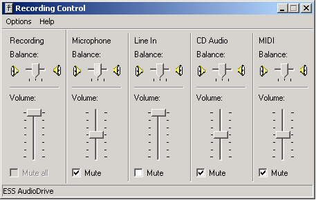
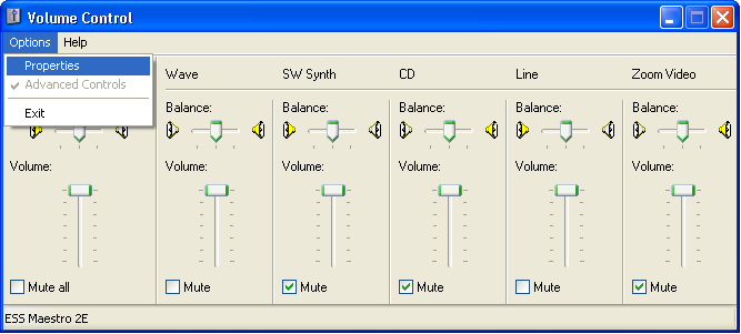
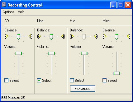
PC setup for the Translator involves turning up and unmuting as needed the main and "Wave" volume control sliders of the PC's regular playback Volume Control panel. It's also good to turn down or mute all the other sliders. (And center the Left/Right controls.)

Double-Click the "xam.bat" batch file, and enter the code "86PL B8W9 YW3L 39TX Y" (translates as "AVID*089*011*053") for testing. The translator accepts the rec.pets-2005a Primary Form (17 characters) or Long Form (96 characters, provided for completeness) as input for translating, 
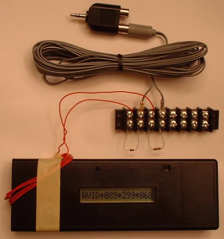
and will transmit for several seconds each entered code. Immediately afterwards, it will send a code which translates as "AVID*089*299*868" for one second, at slightly lower volume. Seeing this code on the display, exact in all digits, indicates a "non-translatable" result from the translation process, but also confirms that the translator hardware is working. Erroneous input, such as a transcription error in a found pet report, is the most likely cause of this. Is it a big problem that a non-translatable result can occur in the translation process? Think of it this way. A transcription error, such as an incorrect digit, in a found pet report made from a standard non-encrypted microchip, or a report made by an AVID scanner from an AVID "Encrypted" chip, or even a report made using a collar tag number, results in an answer from the database of, "Not Registered" or else, some other pet's data. For the rec.pets-2005a format, the vast majority of all possible transcription errors gives a non-translatable error warning instead of a valid translation result. Flagging of most transcription errors is a feature of the Translator method which partially makes up for having to use the long 17-character codes. Wouldn't it be nice if the other transponder protocols supported a way for the registry database operator to tell when a reported code had been corrupted?

You might want to put a label near the display window with the legend "AVID*089*299*868 = non-translatable" as a reminder of this. (This code won't be a real pet's ID, of course; this is one of my specimen chips.)

The "xam.bat" batch file has only one statement in it; it just runs "xam.exe" for you. You can just double-click "xam.exe" instead, but I have found that the "paste" operation, through use of the right mouse button, only works if the batch file is used. Your system may be different. For the batch file to work, it needs to be outside of a zip 
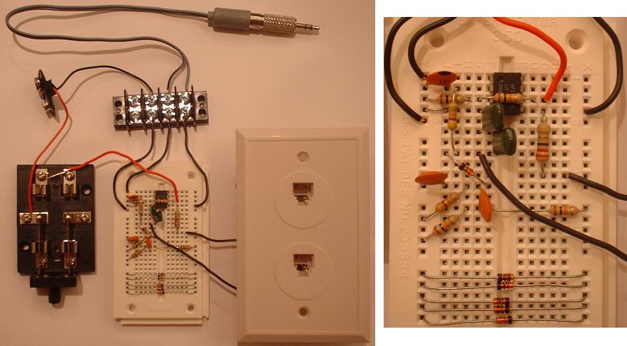
file folder, with "xam.exe" in the same folder. In order to leave the "Avid MiniTracker" turned on continuously, a quality battery eliminator is desirable.

Once again, if you'd like to share your experiences in building the Max Microchip scanner or translator, please post to the rec.pets newsgroup, placing the word "max" in your subject line!

Thanks, Andy Kluck, Max Microchip designer. (E-mail postmasternospam.maxmicrochip.com; leave in the nospam part!)